
Replacing the rear subframe (part 3)
Click on the images to enlarge

I had left the Mini for some time making various excuses for not returning to the garage to finish the job. Finally running out of excuses I returned to the project to take up where I last left off.
I took the old brake pipes and unions to a local motor factors to get some new ones made up. I also bought some exhaust mountings while I was there and some other bits and bobs. They did not have the correct pipes to make up a new fuel line so I would have to get that someplace else.

While attempting to fit the brake pipe and union under the servo unit in the engine bay I did something that I have learned, the hard way, never to do again. I could not get the copper pipe to bend where I wanted it to bend so that it would fit in the tight space and go up into the correct connection point. So I used some pliers to help. Now those of you that are experienced in the art of copper pipe bending will know that you never ever use tools, only your hands. I did not know this and the copper pipe kinked. This means that its now useless because you cannot remove kinks from a copper pipe.
I got lucky because the kink was an inch from the end of the pipe. I took it to another place who cut the pipe at the kink, removed the union, slid it over the pipe and re-flared it for me, for free. Well I did spend a small fortune there on 12ft of expensive fuel line but it's good quality pipe.
Fitting the brake line took time and patience but it felt great when it was on. I re-used the rubber sleeves from the old pipes and fed the pipe behind the front subframe and under the car making sure that it was clipped to the body where it should be. I believe I have an inch or two to play with when I feed it over the rear subframe and into the 3-way splitter.
I then fitted the rear brake pipes 3-way splitter to the rear subframe and connected the brake pipes to it. I tend to use a smidgeon of copper slip grease on the unions to stop them ceasing up, careful not to get it to far forward on the union as it might contaminate the brake fluid when it starts flowing.
Ok, now for the mother of all jobs. Fitting the rear subframe.
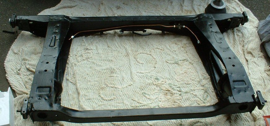
Now as an overview, I've stripped the paint off from under the rear of the car, had an O/S heel board welded on and some plates put in here and there. Plus I've repainted, hammerite'd and undersealed the metal, and I've hammerite'd and undersealed the rear subframe. I've also bought a new subframe fitting kit which includes all the pins, bolts, nuts and bushes I should need. I've fitted all 4 trunnions to the subframe but the locking nylon nuts are not tight so I have some play.
A good tip is to get some gaffer tape and tape up those square holes in the subframe behind the bits where the radius arms will go. They go against the heel board and dirt can get in and start the rusting process. Also take off the brackets that will hold the radius arms in place. Makes life easier.
Now to cut a long story short I've had the subframe on and off several times, cursed the cowboy welder several times, banged around the garage cursing, and kicked a few things. After the dust settled and my patience returned a week later, the following is my proven method for fitting the rear subframe on your own with no help from anyone.
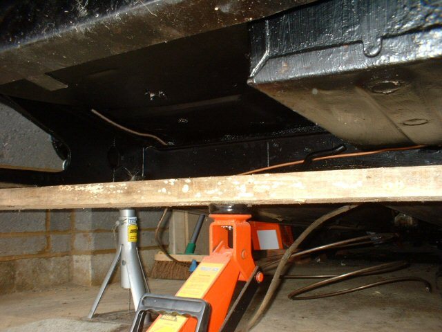
First off find a piece of wood longer than the width of the subframe. Place it across a trolley jack and place the subframe with only the brake lines and trunnions fitted across the piece of wood. Holding the subframe and trolley jack, steer it into position under the raised car and jack it up into place. Now you can use the trolley jack to raise, lower or move the subframe around to suit.
Note: Make sure you feed the brake and fuel lines through the metal clips on your heel board before the subframe is in position and bend them in position so they will be plush against the bodywork and will both come over the top of the subframe. I have not put the fuel line in place yet but I threaded it through the clip so the clip was shaped so I can pull the line out again when the subframe is in place and slide it back in later when fitting the pipe to the car properly.
Jack the subframe into position making sure that all 4 trunnions are facing the correct way as you can not rotate them when in place. Watch that battery box as some subframe moulds tend to catch it on the O/S rubber cone seat rim.
Pick a side and line up the top hole of the trunnion that goes into the heel board (facing the front of the car). Put some copper slip onto the mounting bolt so it will come out easily in the future, and slide it in. The subframe should not be jacked up too tight so you can move the trunnion and bolt around until you feel it get a grip on the hole when you turn it with your fingers. Grab your half inch socket wrench and tighten it up but leave it stuck out about 5mm. Repeat for the top hole on the other side facing forwards.
If like me you may find that the bottom hole on one side is perfectly aligned and the bolt goes in no problem. On the other side though the hole and trunnion may be out by several mm. If the hole is out to the left then what you do is get a G-clamp and place one end on the bottom of the trunnion near the heel board and the other end on the subframe itself and wind it in. The trunnion is sat on two rubber bushes over a metal pin and there is always play in rubber. As you wind in the G-clamp stick the bolt in the hole and rotate it until you feel it get a grip. Stop winding the G-clamp, grab your socket wrench and screw the bolt in. Do not remove the G-clamp until well over half the bolt is inside the heel board.
If your hole was out several mm to the right then you have to take the top bolt out, move the trunnion so you can get the bottom bolt in first, then use the G-clamp method to get the top bolt in the trunnion.
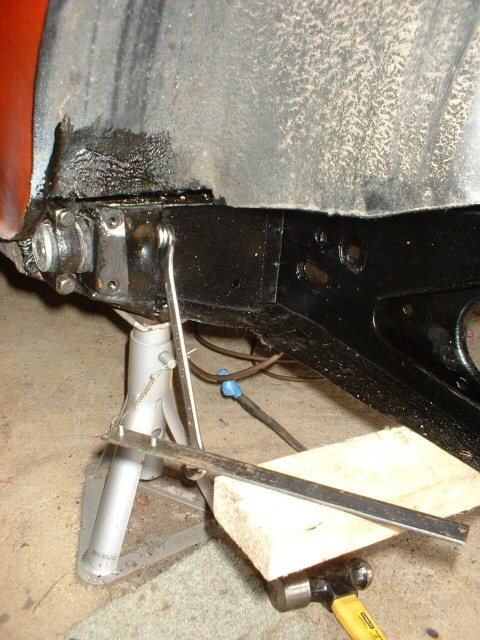
Note: If you look in the picture you will see a special tool made up which looks like a piece of flat metal with two screws threaded threw it. This was made for me to help tighten the trunnions. You may need something similar to stop the outer heads rotating when you later tighten the nylon locking nuts.
Ok this is where I am up to as of mid-August. What happened was that I had to take the subframe off again before I got to where I am now because I had stripped the threads on a trunnion pin by over tightening the nut in a failed attempt to wind one side in to solve my misalignment problem for that one hole. This is before I had hit on the idea of using a G-clamp. I went to a local Mini repair shop and bought a couple of new nylon locking nuts and reused one of the trunnion pins I had taken off the original subframe because there was nothing wrong with it.
The next step is to bolt in the rear two trunnions which bolt into the boot space. If like me, once the front two trunnions are bolted to the heel board, you may find that the back two are not aligned correctly. Oh what fun.
Did you enjoy this article or find the information useful? Help keep Dave and his articles online by keeping him fed with coffee by clicking the link below. Cheers!

Next page - Rear subframe fitted with adjustable suspension
Previous page - Overhauling the radius arms
Back to the Mini Project Main Menu

This website uses cookies. Click here to learn more about how and why we use cookies.